
- SPI SERIAL FLASH PROGRAMMER SCHEMATIC CAPTURE SOFTWARE
- SPI SERIAL FLASH PROGRAMMER SCHEMATIC CAPTURE PC
- SPI SERIAL FLASH PROGRAMMER SCHEMATIC CAPTURE SERIES
- SPI SERIAL FLASH PROGRAMMER SCHEMATIC CAPTURE DOWNLOAD
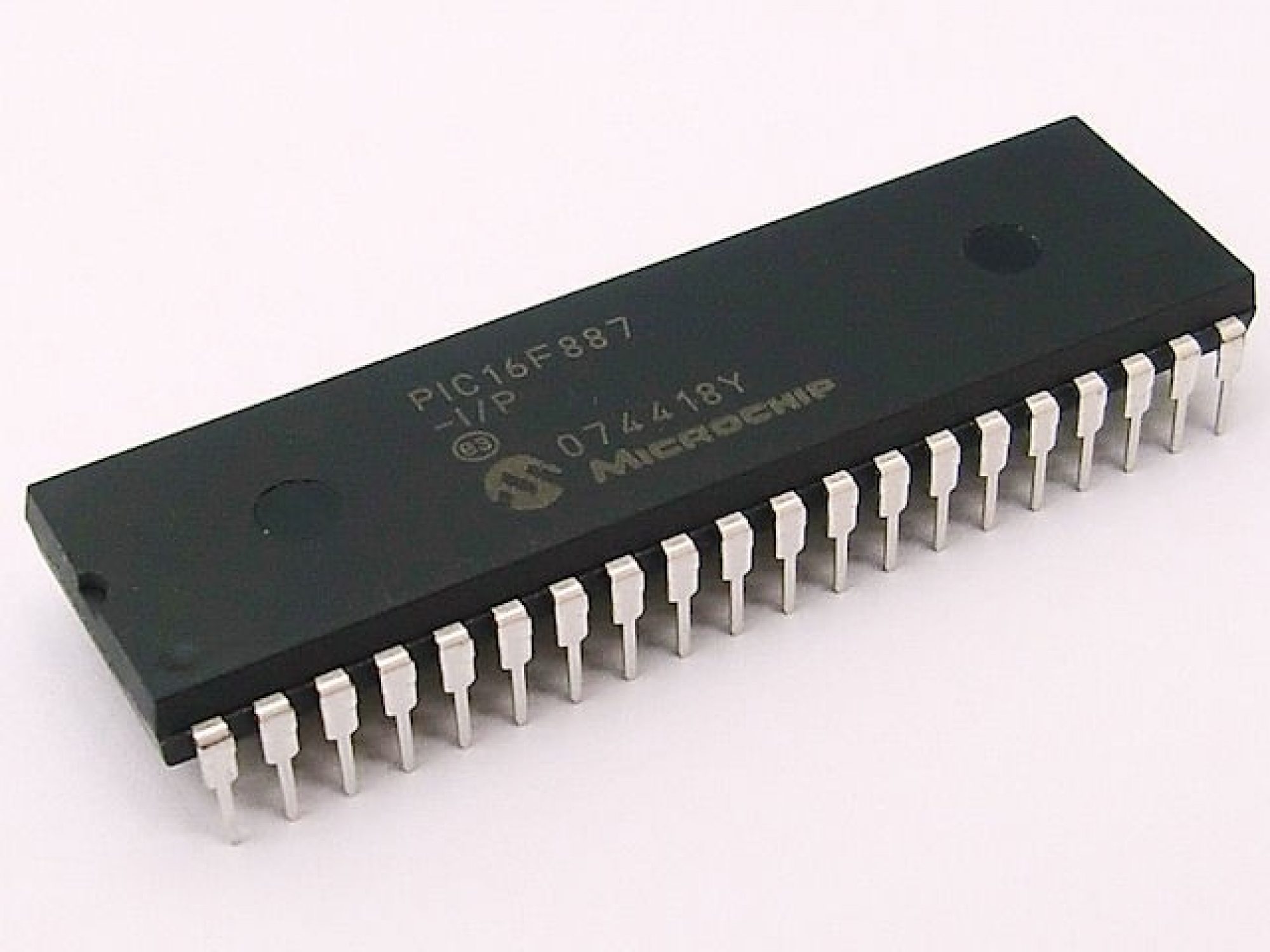
When debugging is complete, the final step is to configure the chip to run independently by selecting the Release option in the drop-down menu in the project toolbar. The PIC 16F887 used later on the Microchip 44-pin demo board does support ICD. Neither the 16F84A nor the 16F690 supports ICD without a special header, which must be connected between the debugger and the chip. Note that not all chips support in-circuit debugging, especially smaller and older chips.
SPI SERIAL FLASH PROGRAMMER SCHEMATIC CAPTURE SOFTWARE
The interaction with the real hardware can be monitored, and hence the hardware and software verified at the same time. However, program execution now takes place in the chip itself. The same module can then be selected from the debugger menu and the program run and debugged using the same tools as used in software simulation (single step, breakpoints, etc.). With the connection confirmed, the program can be downloaded. PICkit2/3 is the low-cost option, which nevertheless offers some very useful features. When the hardware has been connected, the appropriate programmer/debugger is selected from the programmer menu. This system has already been illustrated in Chapter 1 (Figure 1.11), and will explained in more detail in Chapter 7 by examining some Microchip demonstration systems. To facilitate in-circuit programming and debugging (ICD), the board is designed with a six-pin connector, which connects the programming pins on the chip to a programmer/debugger module that is in turn connected to the universal serial bus (USB) output on the host PC. This is also very useful at the prototyping stage, as program modifications can be more rapidly and safely implemented and tested. When a board is produced in volume, the programming can be done as the final stage when the hardware is complete. In- circuit programming is now usually the preferred downloading method, where the chip is left in-circuit after assembly of the printed circuit board (PCB), allowing programming and final debugging in the final hardware. The following table lists the pinout for the SPI interface on J-Link / Flasher when using the J-Link 10-pin Needle Adapter (model 8.06.04).Martin Bates, in PIC Microcontrollers (Third Edition), 2011 4.8.2 In-Circuit Programming and Debugging They can be left open or connected to GND. They should also be connected to GND in the target system *On later J-Link products like the J-link ULTRA, these pins are reserved for firmware extension purposes. Pins 4, 6, 8, 10, 12 are GND pins connected to GND in J-Link. Older J-Links may not be able to supply power on this pin. 17 Not connected NC Leave open on target side.ġ9 5V-Supply Output This pin can be used to supply power to the target hardware. Typically connected to the reset pin of the target CPU, which is typically called 'nRST', 'nRESET' or 'RESET'. 15 nRESET Output Target CPU reset signal (active LOW). Input of J-Link, used to receive data from the target SPI.
SPI SERIAL FLASH PROGRAMMER SCHEMATIC CAPTURE DOWNLOAD
Download aplikasi chat untuk hp nokia e63. 9 CLK Output SPI clock signal.ġ1 Not connected NC Leave open on target side. 7 nCS Output Chip-select of target SPI (active LOW). Output of J-Link, used to transmit data to the target SPI. 3 Not connected NC Leave open on target side.
SPI SERIAL FLASH PROGRAMMER SCHEMATIC CAPTURE SERIES
It is normally fed from Vdd of the target board and must not have a series resistor.Ģ Not connected NC Leave open on target side. It is used to check if the target has power, to create the logic-level reference for the input comparators and to control the output logic levels to the target. Pin Signal Type Description 1 VTref Input This is the target reference voltage. The following table lists the pinout for the SPI interface on J-Link / Flasher.

Supports Tracing on Cortex-A5/A7/A8/A9/A12/A15/A17 Targets.Supports Tracing on Cortex-M0/M0+/M1/M3/M4/M7 Targets.Up to 150 MHz ETM Trace Clock (works with all currently supported devices).SuperSpeed USB 3.0 and GigaBit Ethernet Interfaces for Highest Bandwidth.
SPI SERIAL FLASH PROGRAMMER SCHEMATIC CAPTURE PC


 0 kommentar(er)
